
DIY 4K HOME THEATER MAKEOVER REMODEL // Smart & Stealth Media Room
Learn how to remodel any room into a stealth, smart home theater or media room, complete with projector, motorized screen, smart lighting, and more!
Note: Links below are affiliate links
🛠 Tools Used On Home Theater Makeover:
📦 Materials Used On The Home Theater Makeover:
3” Screws (for framing)
1 ⅝” Trim Head Screws (attaching plywood)
1” Brad Nails (for attaching 1x2 nailer and smaller crown molding)
2” Finish Nails (for attaching larger crown and 1x4 trim)

Pin It!
The Process For Creating Your Own Home Theater:
Step 1: Defining The Issue With Our Old Home Theater
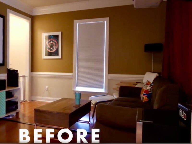
Let’s rewind a bit and take a look at how this home theater or media room started out. Just for some context, this is one of the first rooms you see when you walk into our house and, as you can see, it didn’t look so hot before.
The main issues with the room were a severe lack of light, with no lighting whatsoever in the space compounded by blackout curtains, as well as lackluster cable management, and just an overall cluttered and dark looking space.
My goal with this project was to create a light, inviting living room that could also double as a full-on home theater when we wanted it, but could also be transformed back at the push of a button using some smart home gadgets. Basically, a stealth home theater, if you will.
Step 2: Clear Out The Room Before Construction

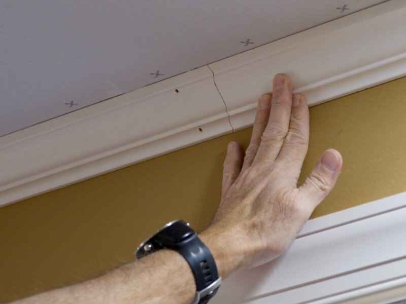
The first step was to get the room cleared out so I could start working in the space, and then I needed to remove the chair rail and crown molding from the room.
Removing trim like this is pretty simple, as it’s usually only attached with a few finish nails and caulk. First, I scored the caulk along all four edges of the trim. If you don’t thoroughly score the caulk, the trim will likely take some of the drywall paper with it when you remove it, so make sure to use a good, sharp knife here.
After scoring, I used this super handy tool, aptly named the Trim Puller, which basically acts as a wedge between the trim and the wall and helps to pry off the trim without damaging the wall behind it. I’ll link to it in the video description below in case you’re interested.
I did still manage to tear the drywall paper in a few spots as I worked my way around the room, but I’ll show you how to fix that later on.
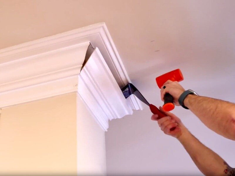
Next, as I mentioned, I needed to remove the crown molding from this room. Whoever built this house really loved their molding, but it had to go to make room for the soffit.
The process for removing this was the same as the chair rail, except this molding was in three pieces. As I got inside the room, I was a little less careful when it came to scoring the caulk, because I knew this entire area would be covered by the soffit I’d be building next.
Step 3: Layout For Soffit Build

Speaking of which, next I could start laying out exactly where I wanted the soffit to go. In case you aren’t familiar with what a soffit is, in this case it’s a small bump out that wraps around the upper corner of the room. I’ve also seen these called bulkheads, but the general purpose is to hide something, whether that’s AC ductwork, plumbing, or in this case, lots and lots of wires.
I decided that I wanted my soffit to have a finished height of roughly 10”, which would give me enough depth for the motorized projector screen I planned to install plus ample space for the recessed lighting and wiring.
I started by making a mark at 8 ¾” from the ceiling, which is where the bottom of the 2x4 ledger that attachs to the wall would sit, and then I set up my line laser even with that mark.
Next, I went around the room and measured from the ceiling to my line laser, just to see how much of a difference there was from one end of the room to the other. As it turned out, one side of the room was close to an inch higher than the other, which is why using something like a laser level is so important in situations like this.
Continuing on with layout, next I figured out where my ceiling joists were located using a stud finder, and the framing on the soffit will attach to these joists.
Unfortunately, there was no ceiling joist to tie in to in this open section of wall, but I came up with a solution for that later on.
Step 4: Constructing Ledger For Soffit Installation

With my layout work done, I could move on to actually framing the soffit, and I started by getting a 2x4 ledger attached to the wall along the perimeter of the room.
To measure the length of the 2x4 I needed, I used this cheap laser measure, which is surprisingly accurate and really comes in handy when you’re working alone.
After measuring, I headed to the garage to cut a 2x4 to length. One tip when purchasing 2x4s for this project is to buy 2x4s as long or longer than the length of the walls in your room if possible. This room, for example, is 12 feet x 13 feet roughly, so I bought mostly 12 foot and 14 foot 2x4s. This allows you to have one straight run on each wall, rather than having to piece together multiple pieces.
I used 3 inch screws for the framing on this project, mostly because screws can be removed if mistakes are made. I did mess with my framing nailer a bit on this first board, but quickly decided to stick with screws.
As you can see, I just lined up the bottom edge of the ledger with my line laser and drove in screws into the studs.
After the first wall, it was really just rinse and repeat around the rest of the room, until I got to the wall opening. I ran the ledger across the opening, which gave me a place to attach my soffit later on.
The other half of the framing was on the other side of this opening, and once again, I referenced my line laser here, marking the height at each end of the opening, and then used the laser measure to get the length.
I cut the pieces to length at the miter saw, cutting the pieces for the two sides and top and bottom of the framing initially, and then screwed them together.
After test fitting, I could attach the framing to the wall, making sure the bottom edge of the frame was in line with my laser and that the face of the framing was plumb. I also made sure to set the framing back ½” from the faces of the columns, which allowed me to cover this area with drywall.
I came back and filled in the framing with blocking, and, since the height was different from one end of the framing to the other, I had to cut the blocks to fit, making sure to check the bottom edge of the framing for level as I went.
Step 5: 2x2 Stud Framing For Soffit Installation
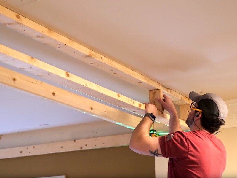
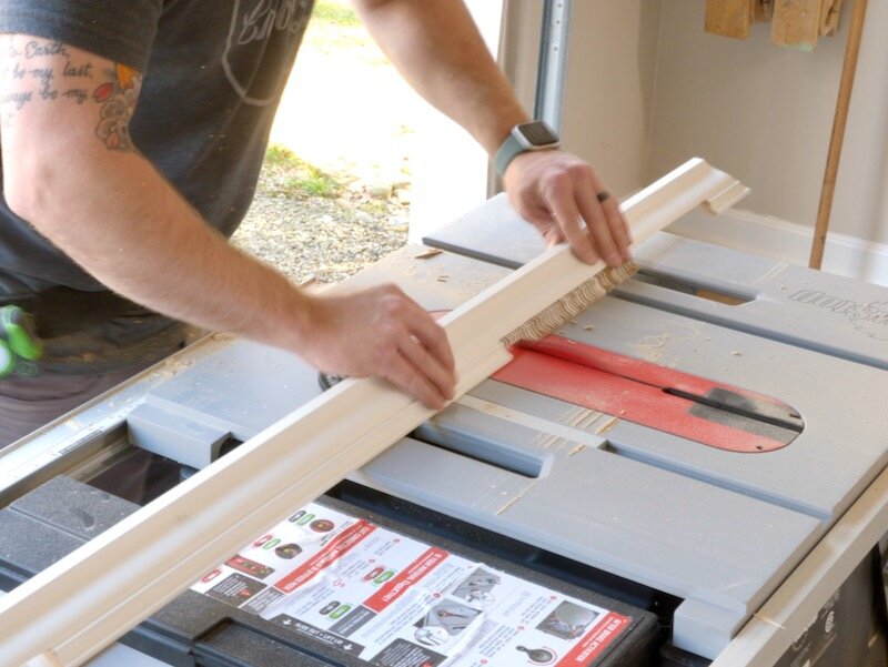
Next up was the 2x2 framing, which mounted to the ceiling. 2x2s typically only come in 8 foot lengths and are usually extremely twisted, so I went ahead and ripped my 2x2s from longer 2x4s using my table saw.
After ripping, I cut the first piece to length off camera and then attached it to the ceiling, making sure to drive my screws into the joists above.
I once again used my line laser for reference, but this time I was running the line vertically, which meant I had to set up the line manually. To do this, I first marked out the distance from the wall were I wanted my line, drove in a screw at that location, and hung my laser from that screw.
I then marked out the same distance at the other end of the wall and just lined up the laser with my mark, which ensured a perfectly straight line across the ceiling, regardless of whether the wall was bowed.
I continued the process on the center wall, running the 2x2 between the first two 2x2s.
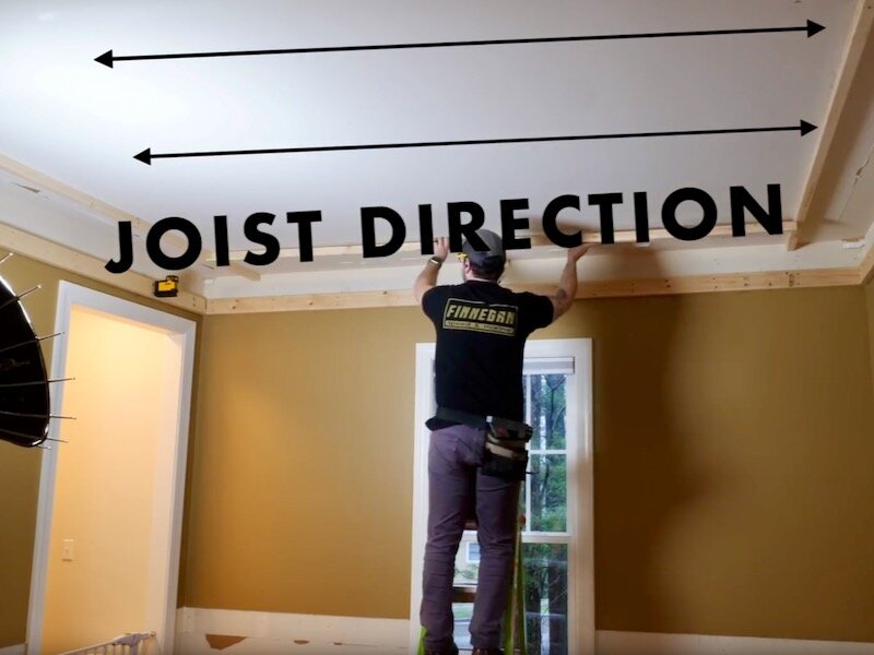
The ceiling joists run parallel to the 2x2 here, rather than perpendicular like with the first two 2x2s. I sized this soffit to line up with the ceiling joist here, so I didn’t need to add any additional framing, but that wasn’t the case with the last 2x2 over the wall opening.
For that, I needed to get a little creative. I first attached the 2x2 to the existing 2x2s with more 3” screws and then also used a few toggle bolts in the middle of the 2x2, which allowed me to attach it to the drywall.
Next, I tied in to the existed 2x4 structure with some 2x4 stretchers, which I added between the 2x2 and the 2x4 framing. Finally, with what was probably some serous overkill, I added one more 2x4 across the wall opening, which supported the 2x4 stretchers from below.
Step 6: Plywood Sheathing Installation

With that, the initial framing was done, so I could move on to doing some sheathing. This whole soffit is made up of two layers of sheathing on both the vertical and horizontal faces, with a base layer of ½” plywood for structure and then a top layer of drywall.
Before ripping the plywood to width, I set up my laser in the same spot as when I added the 2x4 ledger initially and then measured to see how much of a difference there was along the 8 foot length the plywood would be spanning.
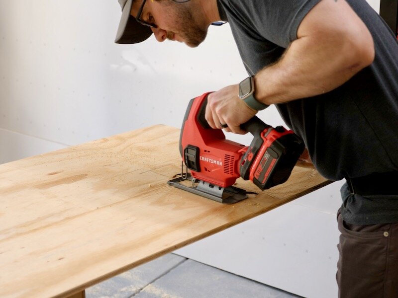
Rather than scribing the plywood to match the measurement, I just ripped it to the narrowest width, again using the table saw. This meant I ended up with a small gap at the top of each piece of plywood, but this really didn’t matter as it was all covered up in the end.
If you don’t have a table saw, you could get your local home center to make these cuts for you and then do any fine tuning with a circular saw.
I attached the plywood to the 2x2 with 1 ⅝” trim head screws, making sure to line up the bottom edge of the plywood with my line laser.
I just continued working my way around the room, cutting the pieces of plywood to length where needed, and using the offcuts to start the next section.
Before moving on, I luckily remembered to double check the area where I’d be attaching the motorized projector screen to see if it lined up with the ceiling joists and, of course, it didn’t. Thankfully, I was able to add a few pieces of blocking to solve this.
With that done, I worked my way around the room one more time, attaching another 2x2 to the bottom edge of the plywood, and this would serve as the attachment point for the sheathing on the bottom side of the soffit.
Step 7: Electrical Work Inside Of Soffit

Next, I could take a break from the building and switch gears to some electrical and wiring. First, I figured out the exact locations where I wanted the recessed LED lights on the underside of the soffit and marked those locations with painter’s tape.
Once that was done, I could work on tapping into the existing electrical circuit in this room and, to do this, I needed to remove the existing junction box so I could run some new Romex.
I ensured that the circuit wasn’t live after turning it off at the breaker, used a reciprocating saw to cut the nails holding the box to the stud, and then removed it from the wall.
Next, I marked out and cut a hole for a 2-gang electrical box, which will house a new pair of switches, one for the recessed lighting and one for the LED strips that will run along the inside edge of the soffit.
Next, I drilled a hole with a hole saw above the ledger board above the outlet I had cut out, and then I could start fishing my Romex through, running the wire down and out the outlet opening and then across the open wall area.
I cut the wire at each light location, leaving about a foot of extra wire on each end so I’d have plenty of room to wire things up later.
I actually screwed up at the beginning of the run and forgot to run wire down to the switch first, so I had to go back and redo that section, but I attached the new work box permanently once I roughed in the wiring there.

Next, I could actually wire up all of the recessed lights, which I picked up on Amazon. They include everything you need except for the service entrance connectors, and they’re pretty much foolproof to wire.
The lights can also be disconnected from the box, which is definitely a nice feature since I was able to wire these up before sheathing the underside of the soffit. I’ll link to the fixtures in the video description in case you’re interested.
Now, depending on how much load you’re going to be adding to your circuit, you should probably run some numbers to make sure the circuit is beefy enough to handle it. In my case, I was just adding a few LED lights, which draw very little power, and then adding a few more outlets for items I was already using in this space, so I knew I was good.
Speaking of which, after the lights were up, I ran another circuit for those additional outlets, including one for the motorized projector screen, the LED strip lights, and the projector itself. The outlet for the LED strips is mounted to the front of the soffit itself, so I went ahead and cut out the opening and installed it, and then I went back and wired up all of the outlets, so that I could test everything out before moving on.
Thankfully, everything worked on the first try, and I’ll show a little more detail on the lighting system later on, including the switches, so stick around for that.
The next set of wiring to work on was for the in-wall and in-ceiling speakers. I decided to add a pair of side surround and rear surround in-wall speakers, as well as a pair of Dolby Atmos ceiling speakers, all from the Dayton Audio line from Parts Express.
After laying out the locations of the speakers, I cut a hole for a low voltage box at the front of the room and then I could start running all of the cables, which took way more time than I anticipated. On the rear speakers, I had to contend with insulation, since these are outside walls, which made things even more challenging.
I should also mention that I used in-wall rated speaker wire, which you should do as well if you want your install to be up to code.
I also ran a fiber optic HDMI cable for the projector while I was at it, but as it turns out, I ran it in the wrong direction, something I didn’t even know was a thing and didn’t realize until I tried hooking up the projector for the first time. But we’ll get to that later.
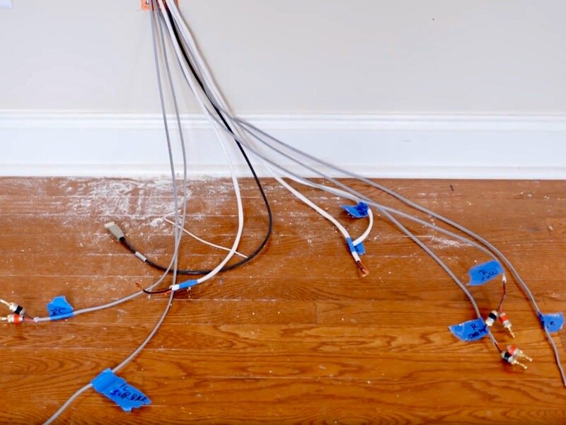
Anyway, this is how the room looked with all of the wiring in, and here’s the cables coming out of the wall at the front of the room, all labeled of course, and I’ll tidy this mess up a little later.
Step 8: Finish Framing Inside Soffit

With the wiring done, I could get the framing finished up with more 2x4 stretchers across the bottom of the soffit. These stretchers ensure the vertical soffit faces are plumb and lock the pieces in place before adding the horizontal soffit sheathing.
I once again called on the line laser and set it up so the laser would land between the plywood and the 2x2 when the soffit was plumb. I could just cut my 2x4 stretchers to fit this space and then attach it with more 3 inch screws.
I continued working my way around the room, adding blocking every two to three feet. I also made sure to leave plenty of space around where I’d be installing the recessed lighting, as well as the in-ceiling speakers.
My buddy Eddie also came over at this point to help with the sheathing, and it was so nice having two sets of hands during this part of the build.
Step 9: Cutting Drywall For Installation

Speaking of sheathing, next it was time to add the drywall to the vertical soffit face, and I used 12 foot long sheets of drywall on this project to minimize the number of seams I had to tape and mud.
After measuring, we cut the drywall to width, first scoring the front face of the sheet, snapping it along the scored area, then finally cutting the piece free by cutting the backer paper.
We cut it to length using the same method and then we could get it attached to the soffit using 1 ⅝” drywall screws, making sure to hit the 2x2s behind the plywood. We definitely went a little overboard with the screws here, running them about every eight inches, but that drywall ain’t going anywhere.
We just worked our way around the room until we had all four faces covered, and then I could prep for the horizontal sheathing.

To do this, I temporarily fastened all of the hanging wiring above where the sheathing would run, as it can create a major fire hazard if this wiring gets trapped between the sheathing and the framing.
Next, we could get the horizontal sheathing installed, and I had already pre-ripped some 18” wide strips from some leftover ½” plywood at my shop, so we started with those.
Step 10: Horizontal Plywood Sheathing For Bottom Face Of Soffit

The main goal here was to maintain a consistent overhang between the front edge of the horizontal sheathing and the vertical sheathing, about 3 inches in our case. Since we knew the vertical soffit was plumb and straight, we just needed to have that consistent overhang to make sure the horizontal soffit was straight.
We marked in 4 ½” from the front edge of the piece using a speed square, to give us a reference line to add our screws, and then fastened the panels with more of the 1 ⅝” trim head screws.
The next wall had a 23 ½” wide soffit section, so I ripped two sections to that width from a sheet of ½” plywood at the table saw.
One thing I haven’t mentioned up to this point is that the soffit isn’t actually the same size on all four walls. The two opposite walls with the projector screen and projector have an 18” wide soffit, while the two opposite walls with the wall opening and smaller window have a 24” wide soffit. This sizing difference was just due to the location of joists in the ceiling above, to which the soffit is attached.
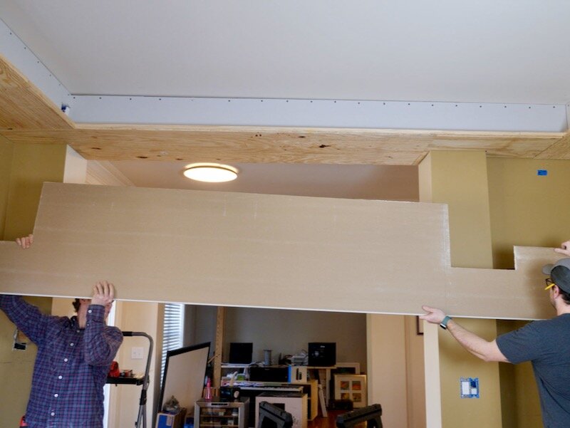
We just continued working our way around the room, switching back to the 18” wide panel on the wall with the larger window, until we got to the wall opening, where we had to notch the plywood around the first column.
We laid out the measurements on the plywood, with it oriented how it would be attached to the ceiling, and then cut out the notch with a jigsaw.
We could then attach it and fill in the last gap on the 18” wide soffit section.
The next area we needed to notch was a little trickier, as this column protrudes from the wall and then jogs back in, but we got it cut with some careful layout.
After test fitting, we actually transferred the layout to the piece of drywall we’d be using on this area, as we knew the fit was good and it would help avoid mistakes.
Once the marks were transferred, we attached the piece to finish off the plywood sheathing.
The next step in the build was to attach a 1x2 nailer to the front edge of the horizontal plywood, which served a few purposes. One, it would help align the plywood edges where the panels met up, and two, it would provide a place to nail on the 1x4 trim I’d be adding later.

We attached the strips with wood glue and 1” brad nails, and I made sure to add a bunch of nails where the panels butted up to each other and even clamped a few of them together while the glue dried, just for good measure.
Step 11: Drywall Installation To Underside Of Soffit

With that done, we could move on to adding drywall to the underside of the soffit, which was definitely one of the more frustrating parts of this project due to the extremely awkward 12 foot long sheets.
First, we cut the piece to width, using the tape measure and utility knife trick, and after scoring the face, we snapped the panel along the cut line and then cut the backing paper.
Next, I cut the panel to length, which I cut from the wrong side, but thankfully it still worked.
This first piece was actually the panel spanning the wall opening with the two columns to cut around, and it was definitely the most difficult piece to fit.
We cut out where we had marked with the plywood template, using a combination of the drywall saw and scoring and snapping, then we carried the panel inside to get it hung in the space.
Off camera, we slapped together a deadman, which is what this t-shaped 2x4 is called, to assist in this, but it really wasn’t that helpful and made things more awkward in my opinion.
The big risk with this particular piece was it snapping in the narrow areas, since drywall isn’t that sturdy when cut to these narrow widths.
It was definitely stressful getting the piece placed but eventually, after some finagling, we got it in place and could add a few screws to hold it.
Once that first piece was in, the other three were relatively easy. We tried the deadman again on the second piece but, once again, it didn’t seem to help much, so we ditched it as we repeated the process on the other two areas.
The last piece of drywall to add was on the other side of the wall opening, and this piece ended up very close to flush with the existing columns, which was a big relief.
Finally, I came back and added a bunch of drywall screws to finish things off, and I used a speciality tip on my impact driver to add the screws here, which ensures the screw heads are just below the surface of the drywall without puncturing the drywall paper.
Step 12: Lighting Cutouts For Smart Can Lights

With the drywall hung, I went ahead and cut some holes for the lights before moving on to taping and mudding, so I could have more light to work with. I used a giant hole saw, sized specifically for can lights, for this and this thing was extremely difficult to use, especially with this long arbor.
I will definitely pick up a shorter arbor if I have to use this hole saw again in the future, as I just about broke my wrists trying to drill all five of these holes.
Of course, the cord wasn’t long enough on this first hole I drilled and I had to order extensions for the lights on this wall, but I could get one of the lights on the narrower soffits hooked up and they looked great.
Step 13: Taping And Mudding Drywall Seams In Soffit

Finally, it was time for a process that I absolutely hate, drywall finishing. I’ve only messed with drywall mudding and taping once, during the shop build, and it’s far from my favorite task.
I started by filling any of the larger gaps between the drywall panels with what’s called “hot mud”, which comes in different curing times. I used 5 minute mud, because I wanted to be able to top coat it with tape and mud quickly, but having that 5 minute window to work in definitely added a lot of stress.
I also forgot to buy a drywall pan to mix the mud in, so I was stuck with mixing it in some random plastic container I had hanging around in the garage.
Once the hot mud set up, I could add the corner bead to the outside edge of the soffit in the wall opening. I used vinyl corner bead, which is attached initially with spray adhesive.
I added a coat to the inside of the corner bead, as well as to the outside corner of the wall, let it dry for a few minutes, and then installed it. I just made sure to flush it up with both faces of the corner and I also used a long level to check for flatness.
Next, I could get to the actual mudding, and I used a pre-mixed dust control mud here, to try and keep the dust down. Pre-mixed mud is usually full of air bubbles and is also a little thick, so it’s best to add a little water and mix it thoroughly, which helps remove some of the bubbles.
All of the screw holes needed to be filled with this mud, and luckily my wife gave me a helping hand on this process while I worked on taping the seams.
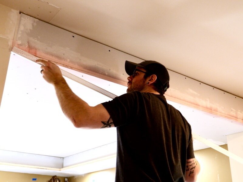
I used this self-adhesive tape, as I figured it’d be easier since I was working overhead, and it seemed to work pretty well. You don’t mud under this tape, and the holes in the tape allow mud to fill in the gap behind the tape.
After taping the seams, I tried my hand at the outside corner and it was challenging to say the least. My main goal on this first coat was just to fill in the area around the corner bead to give myself some room to sand later. I also went ahead and taped and mudded the inside corners under this section, as I wasn’t sure how much the crown molding would hide.
The next day, I came back and added a second coat to all of the joints, using a trowel on the bigger areas. I ended up watching a lot of the Canadian YouTube home improvement guys before this project, and they all seem to love the trowel and hawk, so I figured I’d give it a try.

Shout out to Jeff and his channel Home Renovision and Ben and his channel Vancouver Carpenter. They have a ton of great tips on this kind of work and I’ll link to their channels in the video description.
With that, I called the mudding complete, saving sanding for the very end of the project, so next I could move on to installing all of the trim.
Before doing that though, I needed to cut the opening for the projector screen, which proved to be the second most messy task of this whole project, behind actually sanding the drywall. I’d definitely recommend a respirator here, plus a vacuum in your other hand if you can multi-task. This ended up getting dust throughout our main floor here and my wife was not too happy.

After cutting the hole, we test fit the screen, just as a sanity check, and it fit great, so we could move along with installing the trim.
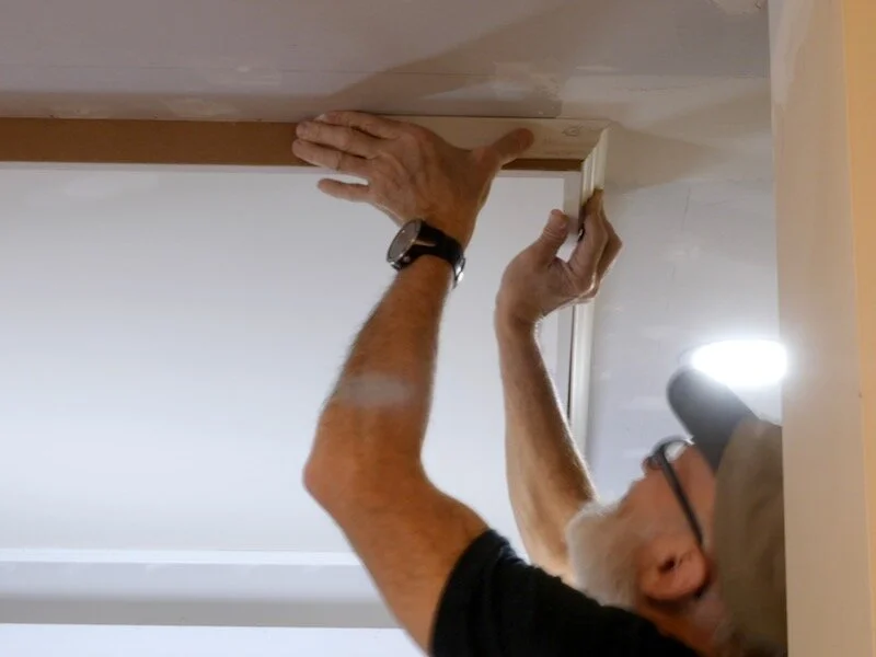
Step 14: Applying Trim To Soffit
We started with the crown molding around the very top of the soffit, and I used a smaller crown for this, just enough to cover the drywall screws really. This was my first time working with crown and I am far from an expert, and there are tons of great videos out there if you want more details.
The basic thing to keep in mind is that you’re always cutting your crown upside down, due to how the angles work out on your miter saw. This can be a real brain wrinkler, but we got the hang of it after a few pieces.
After making that first cut, we test fit the piece and it was too long by a good margin. I had used the laser measure here, but I think there was just too much variability in these drywall corners to get a great reading, so we switched back to the regular tape measure for this trim.
Also, by we, I mean myself and my father-in-law, who was nice enough to help out on the trim install.
After trimming the piece down a bit more, we could get it installed, and we cut these little guide pieces off camera with one of each corner profile cut into them, and this really helped get things aligned in the corners.

Once we had the pieces fitting nicely, we marked where the crown landed on the wall and ceiling then added a few beads of caulk behind the crown in these areas. Caulk is a great adhesive for things like this, and this will help keep gaps from forming over time.
To attach this smaller crown, we used 1” brad nails and made sure to hit framing wherever possible.
Once the first piece was in, it was just rinse and repeat around the other three top edges, and I was able to buy pieces long enough to get all of these out of one piece per wall, which meant no splicing on this first run.
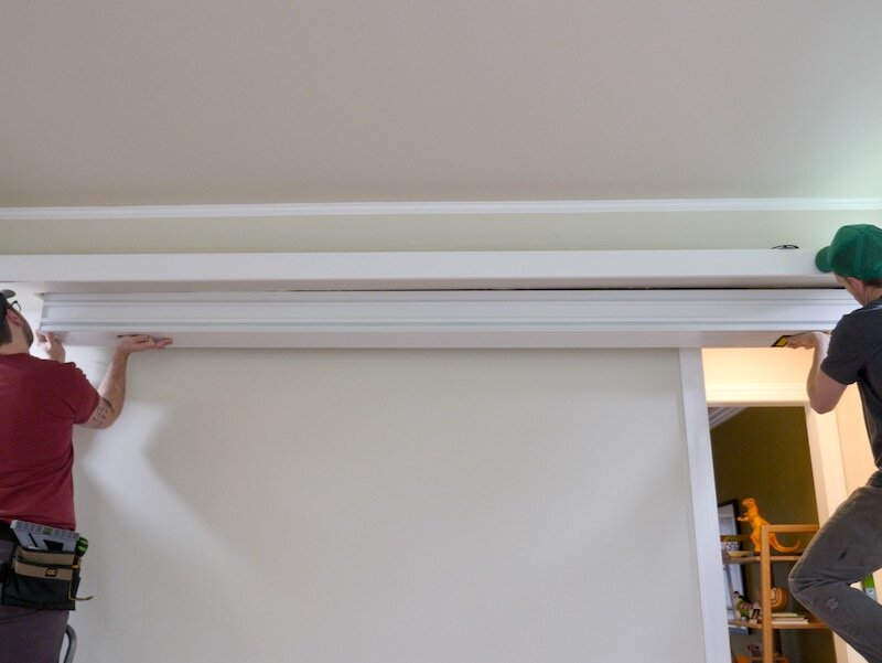
Next, we could add more crown to cover the seam between the bottom of the soffit and the existing wall, and we used larger crown here, as it matches the rest of the house better. We also switched to 16 gauge nails here, since this is larger molding and we could hit more framing.
Once again, we could use one piece on this first wall, but we did have to make a splice cut on the second wall, since it was a little over 12 feet.
To make a splice cut on crown, you can cut the piece at a variety of angles, but we stuck with 45 degrees since the saw was usually already set to that angle. Rather than have the crown sit diagonally like we had it on previously cuts, this time we put the crown flat against the miter saw fence and made the cut.
After cutting the splice on one end, we cut a standard crown cut on the other, with the crown oriented more diagonally across the fence and bed, and then we could attach the piece to the wall.

As you can see, the splice really came together nicely and is basically invisible in the finished space.
We attached the piece to the wall in the same way, with caulk at the ends and finish nails throughout, and then we could move on to the trickiest piece of crown in this room, where it met up with this door casing. This is an oddly tall doorway at 97” high at the top of the casing, and I’m guessing you won’t run into this issue, but we’ll just go over it quickly in case you do.
After some thought, I figured notching the piece out with the table saw would probably give me the best results, so I made a test cut and it worked pretty nicely, but the cut needed to be angled back.

To accomplish this on the actual piece, I oriented the crown in a similar way as on the miter saw, in that kind of diagonal orientation, and then started clearing out material.
My hands were cramping from holding the piece in place and I would have made some kind of jig to hold the crown better but I was in a rush to get this done.
After removing the bulk of the material with the table saw, I cut away the excess with my pull saw and then cleaned up the cut with my block plane, and then I could fit the piece.
Luckily, with just a little bit more fine tuning, the piece fit great, and it blended in perfectly with the door casing. We got it attached to the wall, not before cutting the splice angle on the other end, and then we could get the last long piece of crown installed.
We left the last shorter bits of crown for me to install, since I could do those by myself, so from there, we moved on to the 1x4 trim. This trim covers the front edges of the soffit, which don’t look great, since they’re made up of plywood and drywall edges.
Compared to the crown, this was dead simple, and we just mitered the corners so they’d look nice from below and tacked the pieces in place with more finish nails, with the top edge of the 1x4 flush with the top of the 1x2 nailers.
The last bit of longer trim to install was more of the smaller crown on the underside of the soffit, which again serves to hide those edges and helps to avoid more drywall work. This installed in the same way, but I just wanted to show where we installed it in case you’re trying to follow along at home.
Finally, I could finish out the smaller crown pieces around the bottom of the soffit, which was just more of the same until I got to the return, which is the piece that ends a run of molding like this.
I cut one end of the return piece in the same way as the splice, with the crown flat against the fence, but this time I set the bevel angle to 90 degrees. I thought I had a shot of this, but it’s pretty simple once you get to this point.
To attach the return to the main piece of crown, I used a little wood glue for strength and CA glue to hold the pieces together while the wood glue dried, and I came back later and added a few brad nails for good measure.
Finally, I could install the piece with more caulk and finish nails, and I also added some glue to this outside corner to help things stay together.
Step 15: Preparing Walls For Paint

With the trim installed, I could move on to getting the room prepped for paint, and I started by cleaning up the area where I removed the chair rail. I used a scraper to remove the excess caulk and then used a 5-in-1 tool to remove any loose drywall paper.
A lot of people would apply mud right over this area, but the drywall paper will absorb the moisture in the mud and cause surface finish issues. Instead, it’s best to seal the area with some kind of non-water based primer, either shellac-based or oil-based. I rolled on primer over the entire area, just to be safe.
Once the primer was dry, I came back and prepped for the skim coat of mud by creating dents wherever there were nail holes, which was basically everywhere. These dents ensure the mud can fill in below the surface of the wall, and this gives the mud something to hold on to.

I used 45 minute mud for this skim coat, as I wanted to be able to sand it relatively quickly, and I applied a fairly thick coat along the entire chair rail section, covering any imperfections. I also went ahead and patched any nail holes or other surface imperfections in the wall while I was at it.
Step 16: Cutting Remaining Holes In Soffit For Speakers

While the mud dried, I could get the remaining holes cut in the ceiling, the first of which was for the in-ceiling Atmos speakers. Again, since I was going through drywall and plywood, I used my jigsaw, and I wised up and used the shop vac this time to help with the dust.
Next, I could get the hole for the projector outlet junction box cut, and I also ran the HDMI cable through the junction box and brush plate at this point.
The last holes to cut were for the in-wall speakers, of which there were four. These came with cutout templates, which I aligned using the line laser, and then I cut out the openings using my drywall saw.
I had to remove a decent amount of insulation to get the speakers to fit and was having a hell of a time with this one speaker, only to realize there was actually a nail sticking through that was keeping the speaker from fully seating. After figuring that out, I got the speaker mounted permanently, and finished mounting the rest of the speakers as well.

With those mounted, I could move on to final prep by running caulk along all of the trim, which there was quite a bit of in my case. Thankfully, I’ve gotten better at caulking and this went smoothly.
My wife also gave me a hand again filling all of the nail holes in the trim with spackling, and then I could move on to the part of this project I was dreading most, sanding the drywall.
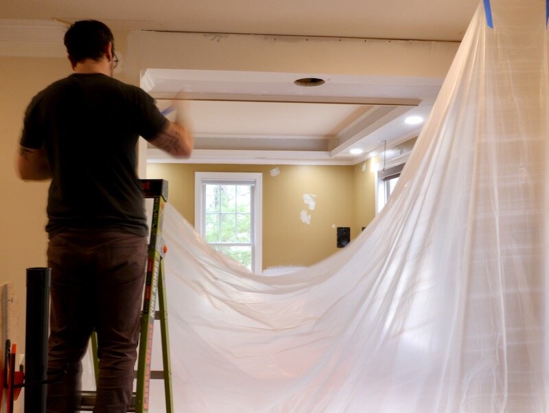
Step 17: Sanding Drywall Before Wall Are Painted
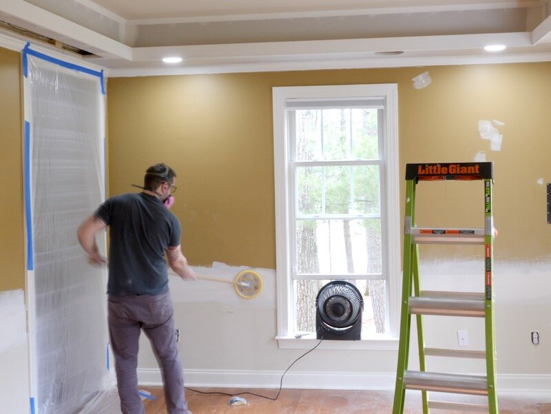
First, I tented off the room using some plastic sheeting, to help contain the dust in this room. I cut a tiny hole in the sheeting to stick my lens through and then set up a fan blowing outwards to help direct the dust outside.
I used a combination of a 9” sanding pad on an extension and a hand sanding block to sand the walls and just tried to feather everything in as well as I could. I also made sure to wear a respirator during this process, as this stuff is nasty and gets everywhere.
After sanding, I cleaned up and then went out of town for a few days, and, due to the tight deadline on this project, I scheduled for painters to come while I was gone.
Thankfully, they did a great job and I could get right back to work once I got home.
Step 18: Motorized Stealth Home Theater Screen Installation
The first thing I did after paint was get the projector screen installed. This screen is the Evanesce Tab-Tension CineGrey 5D model from Elite Screens, and it comes with everything you need to mount it to your ceiling. I laid out locations for the included brackets, and then cut the included threaded rod to the length as specified in the manual.
I then attached the threaded rod to the brackets, attached the brackets to the blocking I had added previously, and got everything prepped for raising the screen into place.
Thankfully, the screen went in place very smoothly with only a little bit of tweaking, and we just tightened the nuts on the threaded rod to secure the screen in place.
Finally, I could test this thing out and it worked awesome, super smooth, fast, and pretty darn quiet. This Cinegrey 5D screen material is ambient light rejecting, which means we can watch our LG CineBeam 4K projector on it in a fairly bright room, which is perfect for this more open space. I’ll link to the projector screen in the video description, in case you’re interested.

The final step in the screen install was to add these end caps, which just cover up the extra opening width at each end of the screen, and I do plan to add an access panel near the left side of the screen in the future, in case I need to make any adjustments to the screen.
Step 19: Testing Motorized Home Theater Tension Tab Projector Screen

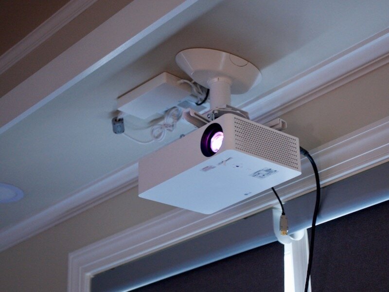
With the projector screen up, I couldn’t help but go ahead and get the projector installed, and I started by attaching the mount to the blocking I had added in this area earlier.
As I mentioned, the projector I’m using in this smart home theater is the LG CineBeam 4K projector, and I’ve got to say, this thing is amazing. One again, just for transparency, LG is sponsoring this video, but that does not change my opinion on this projector.
I’ve been a projector guy for about two and a half years now, since building my previous DIY projector screen, and this LG CineBeam 4K projector is definitely the coolest projector I’ve tried to date.
Essentially, this is an all-in-one smart projector system, including built-in apps for Netflix, YouTube, Amazon Prime Video, and a bunch more. The backlit Magic Remote features Google Assistant voice control, and you can easily adjust your settings via the remote to dial in an awesome image extremely quickly.
You realistically don’t need to connect this projector to anything except maybe a good set of speakers to get a theater-like experience, and the projector features built-in bluetooth if you want to go wireless with your speakers. These features make the LG CineBeam 4K projector, with all of its wireless connectivity, ideal for those of you who don’t want to fiddle with lots of cables or maybe can’t modify your current living space to accommodate lots of wires.
That said, the picture is truly gorgeous and I think really warrants building a dedicated space around it like I did, if you have the option. Add on a good screen and handful of speakers and you’ll create an incredibly immersive environment, and the 30,000 hour rated laser element should last you for many, many years of viewing.
Also, what you’re seeing here is only a 106” screen, and this projector is capable of projecting up to a 140” screen.
All of that from this tiny package, which would blend in on a coffee table or mounted on a shelf behind your sofa, and I think the LG CineBeam 4K projector is a great choice for everyone from home theater novices to aficionados.
Step 20: Soffit LED Strip Light Installation

Next, I could get the LED strip lights installed, and I just went with some basic, inexpensive lights off of Amazon and controlled them with a Lutron Caseta wireless lamp dimmer.
I was considering Philips Hue, since I already have a Hue system in my home, but the Philips strips would have come in at a whopping $360, compared to the $85 I spent on this setup. That said, it would also be really easy to retrofit another system with the outlet I installed if I want to later on.
Speaking of the lights, let’s hop back to the light switches and explain how they work. I wired up this Lutron Caseta switch off camera, which just connects as another point in the recessed lighting circuit. The switch on the left controls the recessed lights, and the other switch, on the right, is actually just a remote, which controls that lamp dimmer.

The beauty of this setup is that it also connects to my smart home system, Apple HomeKit in my case, and also works with the Logitech Harmony remote I used for this setup.
Moving right along, I could get the rest of the speaker system buttoned up, first adding the grilles for the rear surround speakers and then installing the in-ceiling speakers, which are angled and can be turned to direct the sound where you want it.
Step 21: Cable Management For Home Theater

Next, I spent some time cleaning up the cables at the front of the room, and also expanded the wall opening to accept this awesome wall plate, also from Parts Express. This plate allowed me to really tidy up all of the cables except the Atmos speaker cables, which the plate doesn’t have spots for, and the HDMI cable, all of which can just run through the pass-through slot.
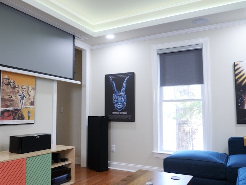
Step 22: Dual Purpose Movie Poster Acoustic Panels Decoration

The walls in this room were looking a little bare, and I figured why not have the artwork pull double duty and help with the sound? How, you might ask? Well, this company called Home Theater Seattle makes these amazing movie poster acoustic panels and they have a huge selection of movies to choose from.
I picked my movies, they made them, and then I could get them hung up in the room. Unfortunately, I couldn’t place the panels exactly where I’d want them for ideal acoustics, which is particularly problematic on the back wall, but these panels definitely tamed some of the echo in the room and they look amazing.
Step 23: Assembling New Love Sac Sactional

Next up was one of the pieces I’ve been most looking forward to as part of this build, our new LoveSac Sactional. Yes, Sactional. In case you aren’t familiar with them, LoveSac is a direct-to-consumer furniture company, and they have two main products; the company’s namesake, the LoveSac, a giant beanbag chair that is supremely comfortable but wouldn’t fit in this space, and the Sactional, a completely modular sofa system.
The entire system is customizable and reconfigurable, and I came up with this layout which just so happened to fit this space with about two inches to spare on either side, maximizing our seating.
One of the coolest features on the Sactional is this built-in charging hub, which features a pair of standard USB ports, a USB C port, and a 120V outlet, all nicely hidden between the arm and seat cushion.
I was also fortunate enough to have the founder of LoveSac, Shawn, out to the house to check out the new space and film some stuff for his vlog, and we actually filmed an interview talking about the process of starting his business and any advice for aspiring furniture builders out there. The full interview will go live on my second channel at the same time as this video, so go check that out if you’re interested.

Next on the list were some new blinds, which I had intended to be smart blinds. Unfortunately, IKEA sold out of their new smart blinds very quickly and are sold out indefinitely at the moment, and the only other options are just astronomically expensive at around $1,000 per window.
Instead, I’m temporarily installing these IKEA blackout roller blinds, which I’ll swap out with the new smart blinds as soon as I can get my hands on them.
Finally, with everything installed in the space, I could start getting the rest of the furniture moved back in, starting with the media console. As you can see, because of that wall plate, I was able to create shorter cables to connect my receiver to the wall and really help cut down on the cable clutter behind the console.
Step 24: Final Details In New Stealth Home Theater
It was at this point that I realized my fiber optic HDMI cable was ran through the walls backwards, but I just wanted to get this darn room setup, so I ran a temporary HDMI cable across to the projector so I could get my speakers dialed in.
My receiver includes a built-in software system that interacts with an included microphone to set speaker levels and make sure nothing is wired out of phase.
After running the test, I could finally get everything set up with the all-in-one Logitech remote.
The Elite Screens projector screen can be controlled via RF or IR, but the IR option was the only one that worked with my Logitech Harmony remote. so that’s what I ended up going with, and after a little fiddling, I was able to get my one button home theater like I’d been envisioning from the beginning.
With that, I could fix the HDMI cable issue off camera and then I could call this home theater complete, at least until I get my smart blinds.